Regional architecture and Ethernet represent the future of vehicle connectivity. New capabilities in vehicles, as well as the shift to aggregating sensors and actuators into regional modules, require high bandwidth and low latency in-vehicle communication networks. Implementing the regional architecture of Ethernet enables the development trend of software-defined vehicles.
Most vehicles today use a cabling and electronic control unit (ECU) architecture called a domain architecture. The domain architecture divides the ecu into different domains based on specific functions, regardless of their physical location in the vehicle.
In contrast to domain architectures, regional architectures organize communications, power distribution, and load control by location rather than by function, as shown in Figure 1. The area module acts as a network data bridge between the vehicle's computing system and local edge nodes such as smart sensors and ECUs. To reduce the vehicle's wiring, the zone module will also distribute power to different edge nodes (by enabling semiconductor smart fuse functions), handle low-level calculations and drive local loads such as motors and lighting.
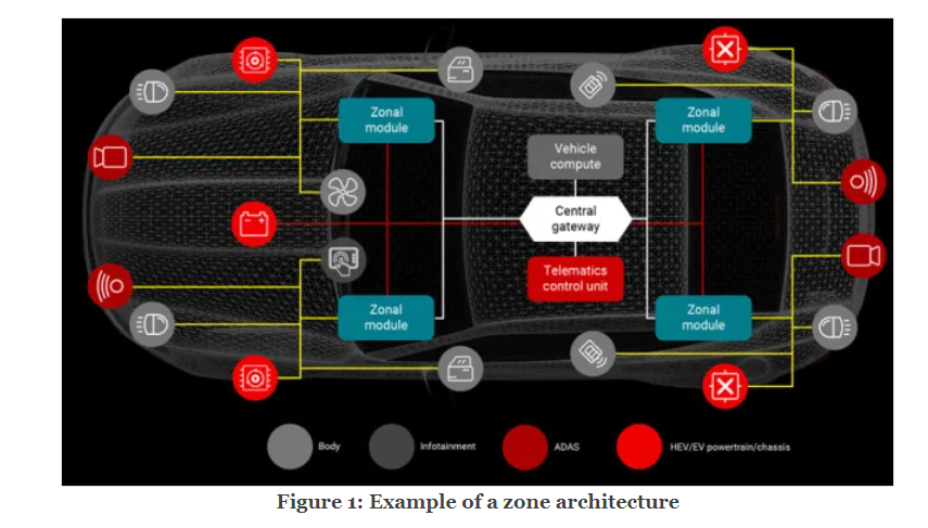
The area module transmits data from individual sensors and ECUs through the edge node communication network, and forwards the combined sensor data to the central computing system through backbone communication. Similarly, the zone module transmits the data received from the central computing system to the individual actuators, again through backbone communication, and again through the edge node communication network. This bidirectional communication between the central computing system and the area modules requires a high-bandwidth and low-latency communication backbone to process the large amounts of data generated by functions such as multiple Advanced driver assistance system (ADAS) cameras, vehicle motion control, and adaptive driving beams.
Bandwidth requirements in a regional architecture
To understand the value of using Ethernet in a vehicle, let's break down Ethernet usage by application. The newly defined Single Pair Ethernet (SPE) supports speeds from 10mbps to 10gbps, as defined by IEEE 802.3g (10mbps), IEEE 802.3bw (100mbps), and IEEE 802. But (1gbps) and IEEE 802.3ch (10gbps). All of these new Ethernet technologies work on a single pair of cables that can communicate over a distance of 15 meters, which is enough to cover the longest link in the vehicle. Ethernet can also synchronize sensor data using IEEE 802.1AS timestamps to achieve low latency.
Although Ethernet is capable of providing extremely fast speeds, these speeds are not required in all situations. For example, communication with gated modules or heating, ventilation, and air conditioning systems does not require a data rate of 100mbps. Alternative network protocols such as 10mbps Ethernet PHY or Controller Local Area Network (CAN) are better suited for low-speed and less bandwith-intensive use cases, while higher speeds are best reserved for sending aggregated camera and self-driving sensor data from regional modules to a central computing system. Figure 2 shows where Ethernet of different speeds is used in a regional architecture.
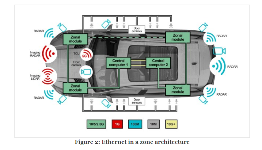
Using Figure 2, let’s take a closer look at the communication speeds used for radar, LiDAR, camera and body applications. Typically, CAN is used to communicate radar data to the zonal module if the radar system-on-chip (SoC) performs the first level of data processing. Sending raw data to the central computing system for processing will extract more information through sensor fusion of various radar sensors. The transmission of such a large amount of raw data requires a higher bandwidth, creating a space for 100-Mbps to 1-Gbps Ethernet in radar and LiDAR.
For cameras, Flat Panel Display (FPD)-Link is the most appropriate protocol when a level of increased ADAS data requires all of the raw data from the front camera for post-processing.
If it is possible to compress the data from the front camera and you don’t need this increased level of ADAS data, 100-Mbps Ethernet is an alternative.
Body-domain modules like door-handle sensors, window-lift control modules and side-mirror control modules traditionally use the CAN and Local Interconnect Network (LIN) protocols to communicate, as a high bandwidth is not required. While designers will continue to use CAN and LIN, the increased use of Ethernet in vehicles also creates a place for 10-Mbps 10Base-T1S multidrop Ethernet. Ethernet is traditionally a point-to-point topology, but 10Base-T1S Ethernet is the first Ethernet standard enabling functionality over a bus topology.
Multi-gigabit Ethernet in a zone architecture
What is the potential evolution of the zone architecture? It begins with aggregating body-domain data, incorporating power distribution and centralizing computing. Over time, zone architectures will start aggregating data from other domains like ADAS. The end goal is to incorporate all domains into the zone architecture. Regardless of which domain the data belongs to, the zonal module and central computing system will still use the same backbone communication network to transfer data.
Body-domain functions require only 10 Mbps or less. But as ADAS functions like radar, LiDAR and cameras become incorporated into the zone architecture, the speed and bandwidth requirements must increase to accommodate the amount of sensor data. A radar sensor typically LiDAR generates 20 Mbps to 100 Mbps. Cameras generate the most: generates 0.1 Mbps to 15 Mbps. LiDAR generates 20 Mbps to 100 Mbps. Cameras generate the most: 500 Mbps to 3.5 Gbps. Today's vehicles typically have four to six radar sensors, one to five LiDAR sensors and six to 12 cameras. If you consider the zone architecture, one zonal module could have two radar sensors, two LiDAR sensors and four cameras. Figure 3 shows how much data is generated by each sensor and the data generated when combining all of these sensors into one example zonal module.

It is the total amount of data generated that is driving demand for 2.5gbps, 5gbps and 10gbps Ethernet from original equipment manufacturers (Oems). The regional architecture requires a backbone communications network capable of transmitting the large amounts of data generated by ADAS sensors to a central computing system. Uncompressed camera data is already beyond the capabilities of current Ethernet, and cameras continue to increase in resolution and pixel count. As cars continue to move towards autonomous driving, the number of sensors will increase. As a result, the bandwidth required to support increased camera resolution and sensors will increase accordingly.
Due to different transition timelines for integrating different functions into regional modules, the Ethernet speeds required by Oems will most likely vary. In general, the more ADAS features in a regional module, the higher the bandwidth requirements.
Using Ethernet as the backbone of the regional architecture, more data can be transferred over the onboard network when the vehicle is connected to the Internet or a remote OEM server. This enables subscription-based services and vehicle diagnostics by remotely performing over-the-air firmware (FOTA) updates. FOTA updates allow for different hardware and software update cycles, which can be asynchronous due to the independence of sensors and actuators from the central compute node. FOTA updates can also drive additional features and safety improvements, rather than waiting for a new model or having to bring the vehicle to work. Both Oems and customers benefit because Oems can control the additional features that update the vehicle after launch, and consumers won't be inconvenienced by going to a dealer to update the firmware.
PHYs in a zone architecture
Ethernet requires the use of PHYs to transmit and receive high-speed data. Automotive Ethernet PHYs eliminate many of the concerns with Ethernet as the backbone of the wiring in vehicles, such as poor signal quality in such a volatile environment. Ethernet PHYs from Texas Instruments (TI) are capable of operating at a range of temperatures from –40°C to 125°C, in compliance with AEC-Q100 Grade 1 standards.
Ethernet PHYs also have to pass Ethernet compliance standards, ensuring that they meet certain interoperability and reliability standards regarding electromagnetic compatibility and electromagnetic interference, as well as IEEE conformance as specified by Open Alliance TC1 and TC12 standards, to work in a vehicular environment. With advanced diagnostic features like signal-quality indication, time-domain reflectometry and electrostatic discharge (ESD) sensors, PHYs are capable of detecting when errors occur and can adjust accordingly. For example, in the event of ESD, the PHY sends an interrupt signal to the SoC/Media Access Control to alert it of the event and then checks other parts in the system.
Ethernet PHYs can also wake up remote ECUs over the SPE cable using the Open Alliance TC10 specification’s wake and sleep technology, which eliminates the need for a separate wire to wake the ECUs from sleep. IEEE 802.1AE Media Access Control Security (MACsec) could also be an important technology to enable the authentication of networking ECUs and to encrypt/decrypt data to avoid cyberattacks, as cyberattacks represent the biggest threat to automotive networking.
TI’s DP83TC812-Q1 and DP83TC814-Q1 100BASE-T1 PHYs have the next-generation features desirable in luxury vehicles, while the smaller DP83TC813-Q1 100BASE-T1 PHY may be appealing in situations when printed-circuit–board space is at a premium. The DP83TG720-Q1 can connect zonal modules to data-intensive features like the central computing system and telematics control unit, leaving headroom for the inclusion of additional features in later models without making intensive changes to the wiring harness. Combined, these PHYs open the door for more advanced and capable vehicles on the road.
About US
Heisener Electronic is a famous international One Stop Purchasing Service Provider of Electronic Components. Based on the concept of Customer-orientation and Innovation, a good process control system, professional management team, advanced inventory management technology, we can provide one-stop electronic component supporting services that Heisener is the preferred partner for all the enterprises and research institutions.