MJE13003 Introduction
The
MJE13003 is a high-voltage, high-speed NPN power transistor specifically for power switching applications that involve inductive loads. With its fast switching capability and optimized fall time, this transistor is well-suited for applications where efficient energy conversion and minimal switching losses are critical.
Commonly used in 115V and 220V SWITCHMODE power supplies, the MJE13003 finds extensive applications in switching regulators, inverters, motor control systems, solenoid and relay drivers, as well as deflection circuits in display technologies.
MJE13003 Pinout
BASE (B) – Controls the transistor's switching operation.
COLLECTOR (C) – Carries the main current to the load.
EMITTER (E) – Provides the current path to ground or the circuit’s return.
MJE13003 Symbol
MJE13003 Footprint
MJE13003 3D Model
MJE13003 Test Circuits
MJE13003 Test Waveforms
MJE13003 Specification
| Parameter |
Value |
| Collector-Emitter Voltage |
400 V |
| Collector-Base Voltage |
700 V |
| Vce Saturation (Max) @ Ib, Ic |
3V @ 500mA, 1.5A |
| Collector Current (Ic) |
1.5 A |
| Peak Collector Current (Icm) |
3 A |
| DC Current Gain (hFE) (Min) @ Ic, Vce |
8 @ 500mA, 2V |
| Power - Max |
1.4 W |
| Transition Frequency (ft) |
10MHz |
| Operating Junction Temperature (Tj) |
-65°C ~ 150°C |
| Package Type |
TO-225 |
MJE13003 Features
Reverse Biased SOA with Inductive Loads @ TC = 100C
Inductive Switching Matrix 0.5 to 1.5 A, 25 and 100C tc @ 1 A, 100C is 290 ns (Typ)
700 V Blocking Capability
SOA and Switching Applications Information
Pb−Free Package is Available*
MJE13003 Applications
Switching Power Supplies
Inverters
Motor Controls
Solenoid/Relay Drivers
Deflection Circuits
Compact Fluorescent Lamps (CFLs)
Battery Chargers
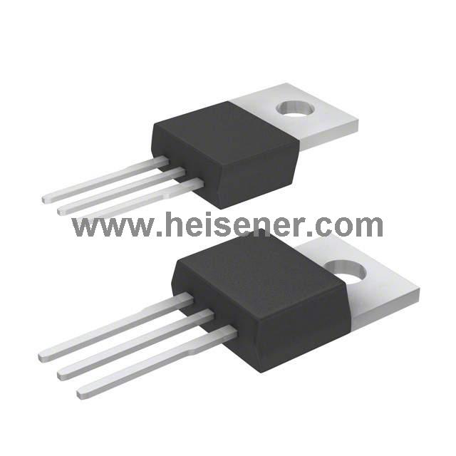
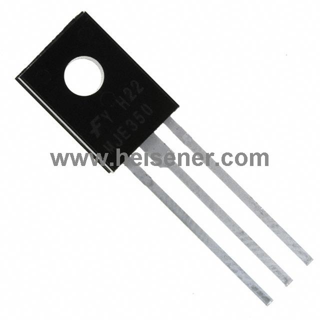
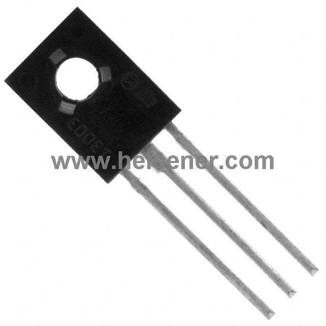
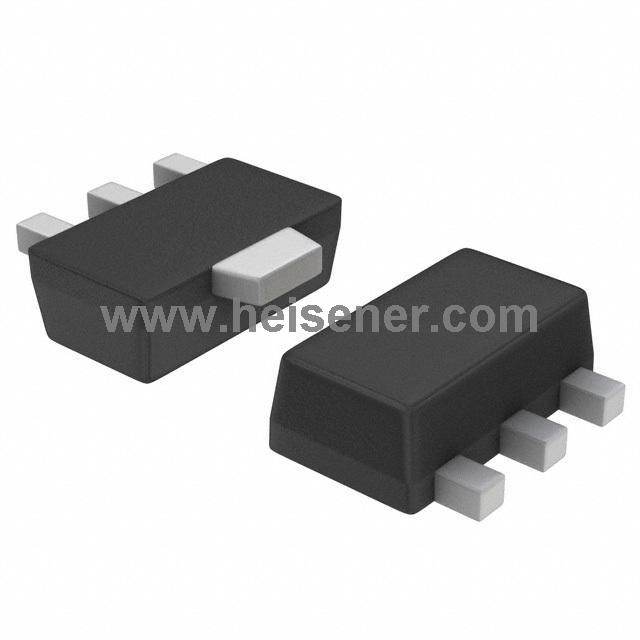
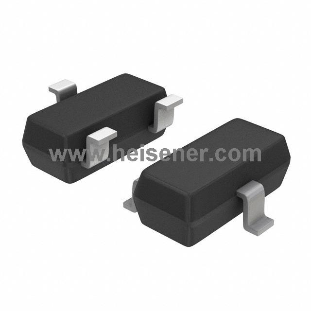
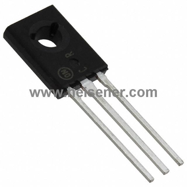
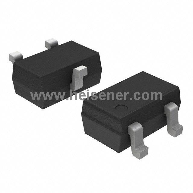
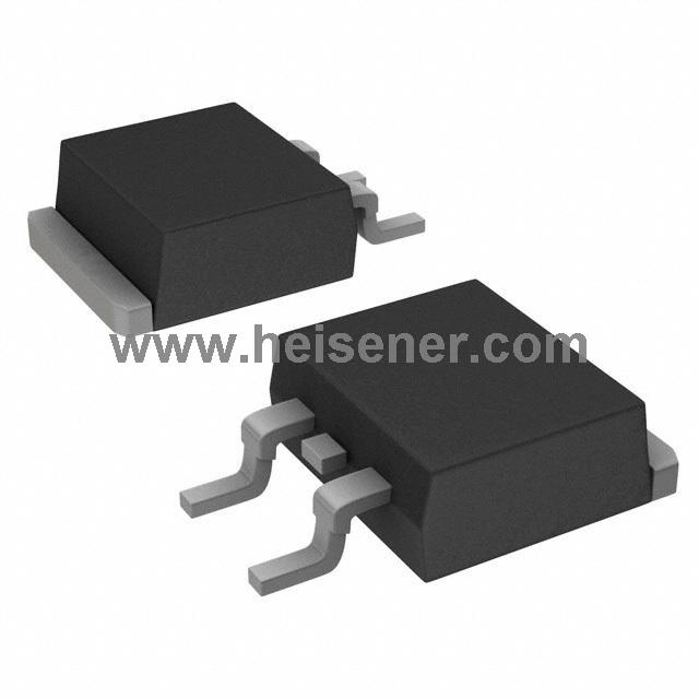
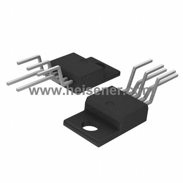
MJE13003 Package
The MJE13003 transistor is available in a TO-225 package, a compact and thermally efficient through-hole package designed for medium-power applications. The TO-225 package provides a sturdy mechanical structure with three leads—Base, Collector, and Emitter—allowing for easy mounting on PCBs or heatsinks.
How to Connect MJE13003?
To connect the MJE13003 transistor, first identify its three pins: Base (B), Collector (C), and Emitter (E). Connect the Base to the control signal through a current-limiting resistor to regulate switching. Attach the Collector to the positive side of the load, such as a motor or LED circuit. Finally, connect the Emitter to the negative terminal (ground) to complete the circuit. When the control signal is applied to the Base, the transistor switches on, allowing current to flow from the Collector to the Emitter, powering the load.
FAQs
What is the MJE13003 transistor used for?
The MJE13003 is a high-voltage, high-speed NPN power transistor commonly used in switching regulators, inverters, motor control, relay drivers, and power supply circuits.
What is the pin configuration of MJE13003?
The MJE13003 has three pins: Base (B), Collector (C), and Emitter (E). The Collector is at the center, with the Base on one side and the Emitter on the other.
What are the alternatives to MJE13003?
Common alternatives include MJE13001, MJE13002, and MJE13005, depending on the voltage and current requirements.