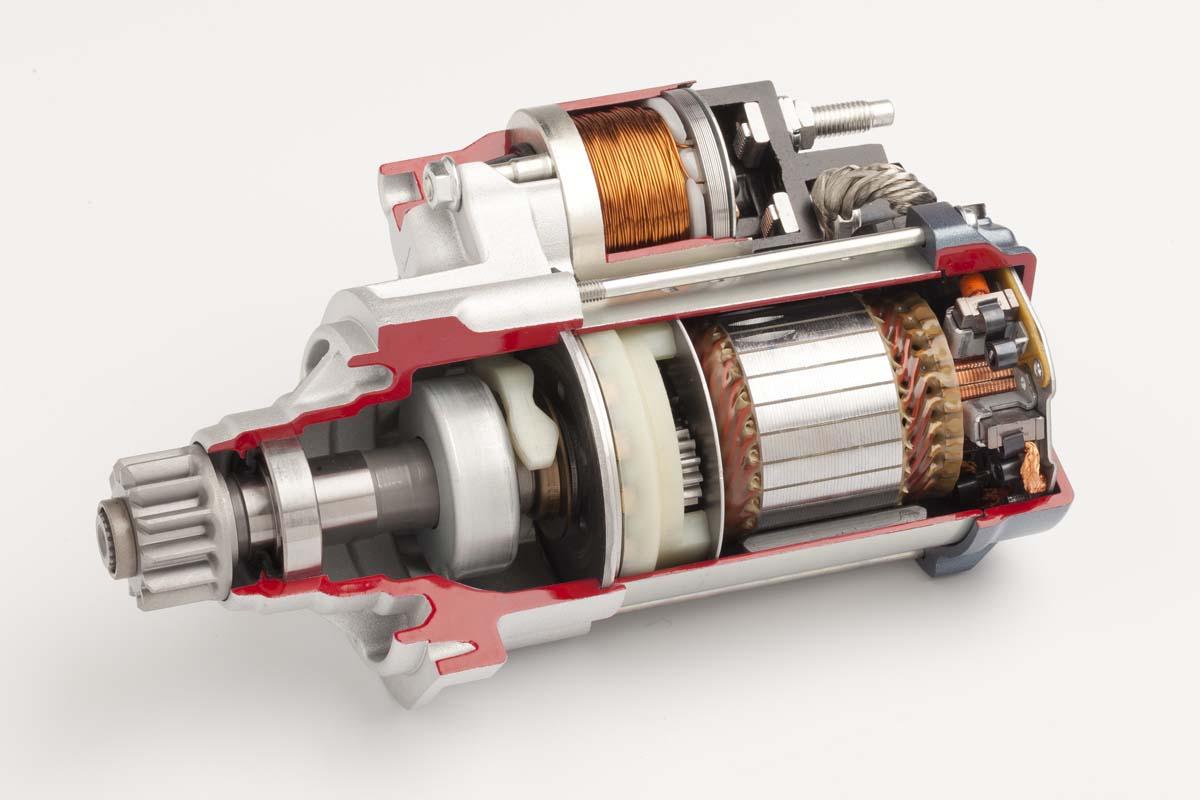
In motor applications, inverters or converters must be used for power conversion, and the use of high-isolation DC/DC converters will help improve the stability and safety of motor operation, which is particularly important for high-power and high-speed motor systems. In this article, we will introduce the technologies related to IGBT/MOSFET/SiC/GaN gate driven DC-DC converters, as well as the functional features of a series of high isolation DC/DC converters from Murata.
Isolation ensures stable operation of high power converters
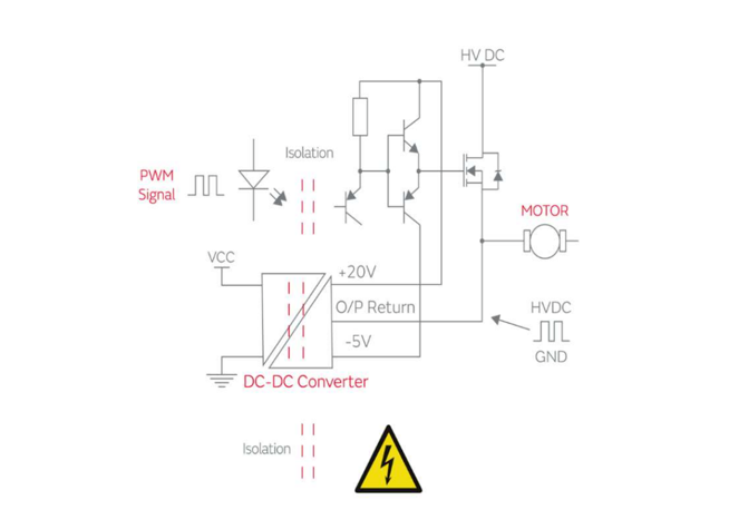
At high power, inverters or converters typically use a "bridge" configuration to generate power-frequency AC or to provide bidirectional PWM drive for a motor, transformer, or other load, which can be a half-bridge, full-bridge, or triequal configuration. Bridge circuits typically include IGBTs or MOSFETs (including SiC and GaN) as "high-side" switches whose emitters/sources are switching nodes at high and high frequencies. Therefore, the gate-driven PWM signal using the emitter/source as a reference and the associated drive power rail must be isolated from ground electricity.
Other requirements for high power converters are that the drive circuit and associated power rail should not be affected by the high "dV/dt" of the switching node and have a very low coupling capacitance. In many cases, the bridge circuit needs to be isolated from the control circuit with a safety mechanism rating, so the drive circuit isolation barrier must be robust and not show significant degradation due to partial discharge effects during the design life.
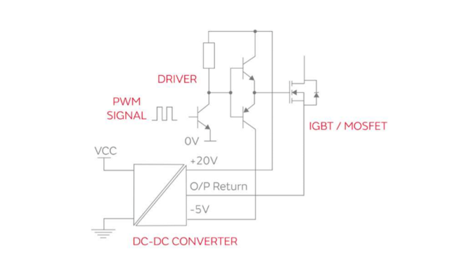
The positive supply rail voltage of the gate drive circuit should be high enough to ensure that the power switch is fully saturated/enhanced without exceeding the absolute maximum voltage of its gate. For example, IGBTs and standard MOSFETs will be fully on at 15 V drives, but typical SiC MOSFETs may require a voltage closer to 20V to be fully enhanced.
For the off state, 0 V on the gate is sufficient for all devices. However, a negative voltage, usually between -5V and -10V, enables fast switching controlled by a gate resistor. The on-state gate threshold for IGBTs is a few volts, which is typically 5V, but SiC and GaN can be as low as a little over 1 volt.
The negative gate drive also helps overcome the collector/drain effect on the gate "Miller" capacitance, which injects current into the gate drive circuit when the device is turned off. During a shutdown, the collector voltage rises rapidly, causing a current spike to flow through the Miller capacitor to the gate, which causes an opposite positive voltage across the gate resistance. Driving the gate to a negative voltage mitigates this effect. Igbts and all types of MOSFETs have the same effect.
The power requirements of a DC-DC converter drive supply, whose DC-DC conversion only provides average DC current to the driver circuit, with peak current provided by the capacitor of the near-drive circuit for charging and discharging the gate capacitor per cycle, need to account for derating and other losses in the drive, the Qg of SiC and GaN is lower than that of IGBTs, but the frequency can be very high.

Highly isolated DC/DC converters designed for gate drive applications
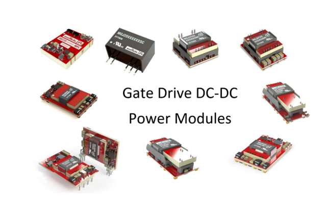
Murata has introduced a range of high isolation DC/DC converters developed by Murata Power Solutions, among which the MGJ series DC-DC converters are designed for gate drive applications to meet the high isolation requirements common in bridge circuits used in motor drives and inverters. Designed to provide optimal drive voltage and isolation for these "high-edge" grid drive circuits. The grid is fully charged and discharged at each PWM switching cycle, regardless of the positive and negative drive voltages, which correspond to equal positive and negative average currents and peak currents. If the output load has unequal currents (for example through additional protection circuits), the voltage may not remain within the expected tolerance range.
The absolute values of the gate drive voltages are not very critical, as long as they are above the minimum required for switch enhancement, appropriately below the breakdown level, and dissipation is acceptable. Therefore, if the DC-DC input is nominal constant, the DC-DC converter that provides the drive power may be of a non-regulated type, such as the MGJ1 or MGJ2 series. However, unlike most DC-DC applications, the load is fairly constant when the IGBT/MOSFET is switched at any duty cycle. Or, when the device is not switched, the load is close to zero. Simple DC-dcs usually require minimal load, otherwise their output voltage will increase dramatically and may even reach gate breakdown levels.
This high voltage is stored on a high-capacity capacitor, so when the device begins to switch, it may experience gate overvoltage until that level drops under normal load. Therefore, a DC-DC with a clamping output voltage or very low minimum load requirements should be selected.
The IGBT/MOSFET should not be actively driven by the PWM signal until the drive circuit voltage rail reaches the correct value. However, when the gate drive DC-DC is powered on or off, even if the PWM signal is inactive, transient conditions may occur that cause the device to be driven, resulting in breakdown and damage. Therefore, the DC-DC output should perform well when powered on and off, and rise and fall monotonically.

Insulation performance testing is very important for high voltage systems
Isolated DC-dcs for "high-side" IGBT/MOSFET drivers can see the switching "DC link" voltage across their barrier. This voltage can reach thousands of volts, with very fast switching edges above 10 kV/μs. The latest GaN devices may have switching speeds of 100 kV/μs or more, and they can generate 200mA of current with only 20pF and 10 kV/μs. This current finds an uncertain return path through the controller circuit back to the bridge, resulting in voltage spikes on the connection resistors and inductors that can disrupt the operation of the controller and the DC-DC converter itself, hence the need for low-coupling capacitors.
High side switch emitter is a high voltage, high frequency switching node, from DC-DC input to output can see the full HVDC link voltage continuously switching at PWM frequency, the frequency may be high, the rate of change is also high, IGBT can reach about 30 kV/µs, MOSFET is about 50 kV/µs. SiC/GaN is about 50+++ kV/µs, DC-DC input-output isolation has a coupled capacitor (Cc), which has a high switching voltage at both ends, so there will be a pulse current flowing through it, which may interfere with sensitive input pins. A common mode transient immunity (CMTI) test can be used to give an indication of this fault level.
In some cases where the isolated DC-DC is powered by another linear or switched mode converter, high transient currents may cause the isolated DC-DC input to overshoot. If the maximum input voltage separating the DC-DC is exceeded, damage may occur. In this case, it may be necessary to use a Zener diode at the input as protection.
In order to ensure the safety of the power conversion process, the DC-DC can be part of the safety isolation system, for example, according to the UL60950, 690 VAC system to meet the reinforced insulation, the need for 14mm creepage distance and electrical gap, the isolation voltage needs to be verified with a single instantaneous voltage that is much larger than the operating voltage, such as holding for one minute. In addition, depending on functional needs, in "high side" applications, DC-DC input to output can see the full HVDC link voltage continuously switched at PWM frequency. In this case, a single transient voltage test of only one minute is not a good isolation indicator, and a partial discharge test according to IEC 60270 is the only way to ensure.
The discharge occurs because the breakdown voltage of the small void (~3kV/mm) is much lower than the breakdown voltage of the surrounding solid insulator (~300kV/mm), and this "starting voltage" can be measured and used to define the maximum operating voltage to ensure the long-term reliability of the insulator. Partial discharge will not cause significant damage in the short term, but the phenomenon of partial discharge will reduce the insulation performance when used for a long time.

Complete and diverse MGJ series DC-DC converters
The MGJ series DC-DC converters from Murata are ideal for supplying "high side" and "low side" gate drive circuits for IGBTs and MOSFETs in bridge circuits. Selecting asymmetrical output voltages enables optimal drive levels for optimal system efficiency and EMI. The MGJ series is characterized by meeting the high isolation and dv/dt requirements common in bridge circuits used in motor drives and inverters. Recommended applications for the MGJ series include inverters and backup batteries on new energy sources (such as wind and solar), as well as high-speed and variable speed motor drives, with key parameters to meet application-specific technical requirements.
The MGJ2 SIP in the MGJ series has a total output power of 2W and provides +ve and -ve gate drive voltage outputs including +15V/-15V, +15V/-5V, +15V/-8.7V, +20V/-5V, +18V/-2.5V, using the traditional dual-winding method. Additional special outputs can be provided by varying the number of turns, while the MGJ2 industrial grade temperature rating and construction provide a long service life and reliability.
The total output power of MGJ3 and MGJ6 series is 3W and 6W, using patented technology, the output voltage can be flexibly configured, such as 20V/-5V (15V+5V, -5V), 15V/-10V (15V, -5V-5V), MGJ3 and MGJ6 disable/frequency synchronization pins simplify the EMC filter design. Its protection functions include short circuit protection and overload protection.
The MGJ1 and MGJ2 SMD have a total output power of 1W and 2W, and use an internal Zener diode to provide specific +ve and -ve gate drive voltages. Including +15V/-5V (from a single 20V output), +15V/-9V (from a single 24V output), +19V/-5V (from a single 24V output), other special outputs can be provided by changing the Zener diode. MGJ1 and MGJ2 industrial grade temperature ratings and construction provide long service life and reliability.
Conclusion
DC-DC converters for gate drive power supply are critical to the safety and stability of motor operation, especially for high voltage and high frequency systems. Murata has launched a series of DC-DC converters for different power, coupling capacitance and package specifications. The MGJ series is ideal for supplying "high side" and "low side" gate driver circuits for IGBT and MOSFET in bridge circuits, and provides strong isolation and insulation properties to ensure the stability and safety of system operation. Will be your ideal solution for developing motor drive applications.
About US
Heisener Electronic is a famous international One Stop Purchasing Service Provider of Electronic Components. Based on the concept of Customer-orientation and Innovation, a good process control system, professional management team, advanced inventory management technology, we can provide one-stop electronic component supporting services that Heisener is the preferred partner for all the enterprises and research institutions.
